The movement
The movement

"UPPER" MOVEMENT
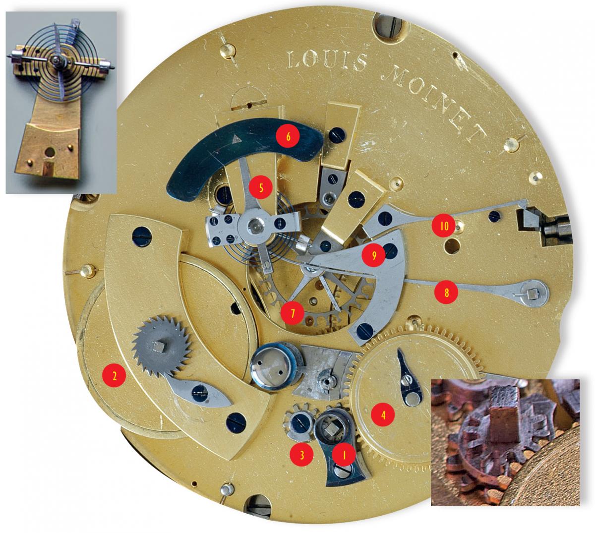
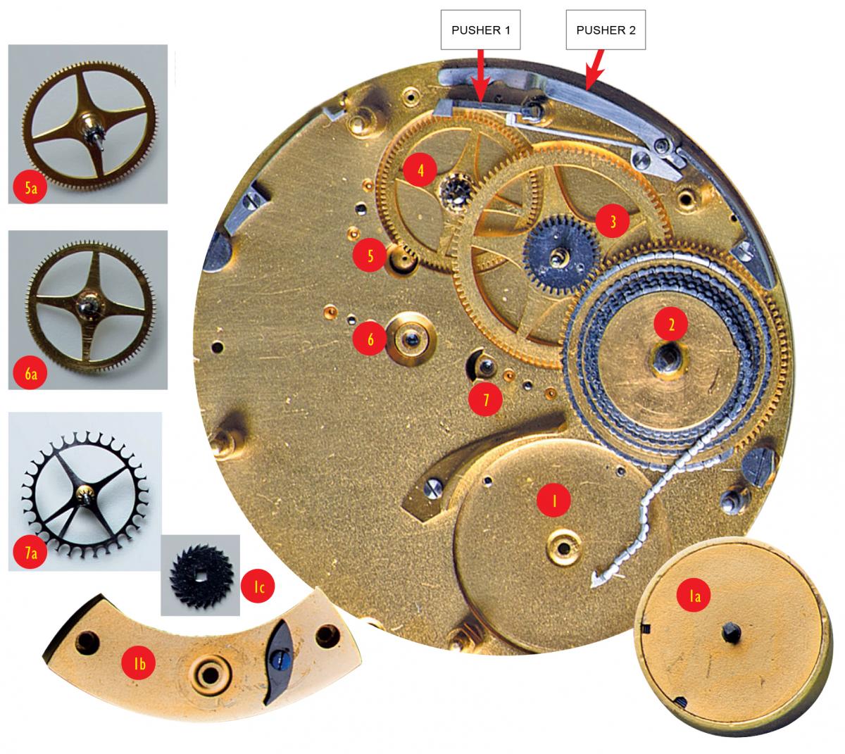
Before looking at the parts in greater detail, we can immediately see the high-quality finish of the movement, which is made from polished steel and blued screws. Next, we can note that this is a fusee movement where the square end of the shaft (1) is used to wind the spring fitted inside the barrel (2). The barrel is placed relatively highly up, suggesting that this instrument requires a powerful spring.
There is a stopwork mechanism (3) on the fusee shaft (1). As we can see from the diagram in the bottom right, a wheel has been fitted over the square shaft and gears with the toothing of some kind of barrel (4). On this barrel is an index, which could well be a power reserve indicator…
The regulating mechanism (in this case a foliot and balance-spring – see top left diagram) is fixed to the balance-cock (5) and at the end of the index there is a blued bar (6). In the centre, there is a wheel similar to a cylinder escape wheel (7). We can also see a blocking lever (8) and a safety mechanism for the blocking lever (9). Finally, we have a return spring (10) for one of the push-pieces.
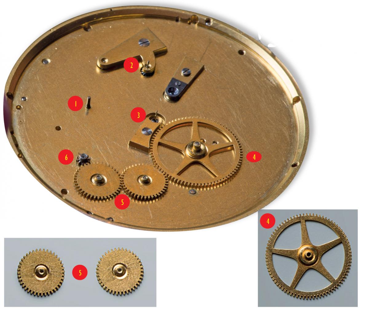
"LOWER" MOVEMENT
The under-dial work is quite simple.
We can see:
We can see:
1) A pivot for the hand of the top left subdial
2) A pivot for the hand of the top right subdial
3) A pivot for the large central hand
4) A wheel for the 24-hour hand (with 80 teeth)
5) 2 relay wheels (each with 40 teeth)
6) A pinion (with 10 leaves) on the fusee shaft that drives the train to the 24-hour wheel
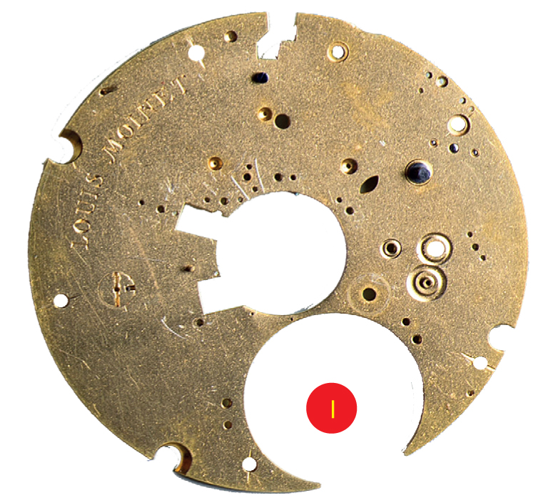
TRAIN ON THE BOTTOM PLATE
1) Space for the barrel 1a) Barrel 1b) Barrel bridge 1c) Winding ratchet
2) Fusee and chain
3) 1st wheel that supports the 60 minutes hand (top left subdial)
4) 2nd (intermediate) wheel
5) Pivot for the 3rd wheel that supports the 60 seconds hand
5a) Wheel supporting the 60 seconds hand
6) Pivot for the 4th intermediate wheel
6a) Intermediate wheel
7) Pivot for the escape wheel that supports the central hand
7a) View of escape wheel from below (1)
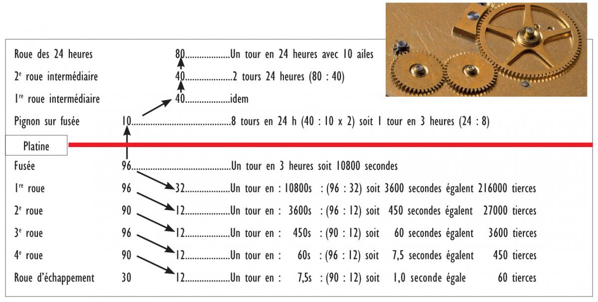
SIZES AND GEAR RATIOS
Given the revolution of the 24-hour wheel, which supports the hand for the bottom subdial (Fig. 27), and that all the ratios are either 8 or 7.5, we can conclude that the 1st wheel completes one revolution every hour and thus supports the 60 minutes hand (top left, Fig. 27). Consequently, the 3rd wheel completes one revolution every 60 seconds and supports the seconds hand (top right, Fig. 27).
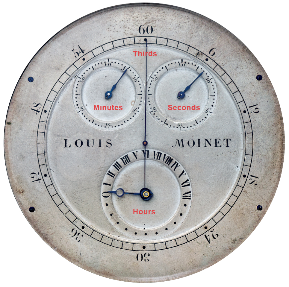
As we noted, the escape wheel is located at the centre of the movement and completes one revolution per second. It therefore supports the large hand that points to the outer circle of 60 'railway'-style markers, which are divided into units of 6. This outer circle marks what were known in French as 'tierces' ('thirds' in English). This term was previously used to denote one sixtieth of a second but subsequently disappeared with the introduction of decimalisation, which instead divided seconds into tenths and hundredths.
As we can see, this escape wheel has 30 teeth and, in view of the type of escapement that I will discuss in greater detail below, each of the teeth provides 2 vibrations (i.e. 60 vibrations per turn). The hourly frequency is therefore 216,000 vibrations/hour (V/h) (3,600 x 60), or 108,000 oscillations.
The period is 0.01/3 of a second (3,600:108,000), which is clearly exceptional for a mechanical device of that time.